
Under-Stairs Storage Drawer Bank Plan - 3 Full-Extension Drawers Fitted to Your Stair Slope
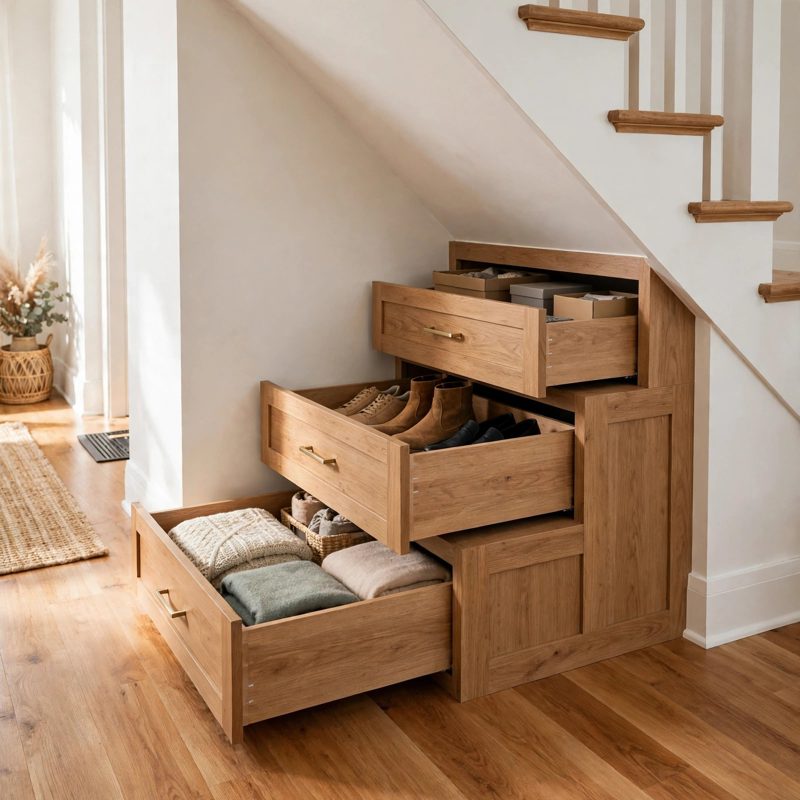
Not a standard off-grid kit - top-of-the-line, above and beyond the old style - safer by design, and every claim below names a real feature drawn into the plan itself.
THE BUILD: a built-in triangular-profile drawer bank that lives under a staircase - a floor-standing carcass with a sloped top following the underside of the stairs, three bays of 19 in inside width, and three full-extension drawers whose fronts rise with the slope at 12, 27, and 42 in and whose boxes are 8, 23, and 38 in tall, for 12.92 cubic feet of drawer storage in the worked example. This is fixed, anchored cabinetry fitted to a measured stair slope - distinct from under-bed storage drawers, which are loose low boxes on casters; nothing here rolls, and the bank is screwed to wall studs and the floor.
SAFER BY DESIGN - THE UNDER-STAIR FAILURES ARE DESIGNED AGAINST: (1) CUTTING THE STAIRS is prohibited absolutely and in print: the plan forbids cutting, notching, drilling, or shaving any stringer, tread, or riser, and instead spends a 1-1/2 in clearance allowance at every bay, checked with a gauge block at three separate gates - if your clearance is short, the drawer front gets shorter by the worksheet formula, never the staircase. (2) HIDDEN WIRING AND PLUMBING are answered with a staged opening: scanner first, one 6 in inspection hole viewed with a light and mirror before any enlargement, and a printed stop rule - a service found in the footprint shrinks the bank, moves it, or waits for a licensed trade. (3) TIPPING is answered with anchoring and honesty: the rear rail is screwed into at least two wall studs with #10 x 3 in anchors (1-3/4 in bite), the plinth is screwed to the floor, and the plan states plainly that slide stops do not prevent tipping - anchoring plus the printed one-drawer-at-a-time rule is the defence, and an unanchored install fails the final gate. (4) DRAWER BOTTOMS BLOWING OUT is designed out: every bottom is 1/4 in plywood captured in a groove so it bears on a wood lip around its whole perimeter, and the two deep drawers add a centre support cleat under the bottom that halves the unsupported span. (5) SLIDE SCREWS EXITING OR PULLING OUT are answered with a reach-checked schedule for every screw in the build, including the drawer-member screw specified at #8 x 1/2 in (about 7/16 in bite, tip about 5/16 in short) because that is the joint where a longer bag screw exits the box side.
EVERY MEASUREMENT VERIFIED TWO WAYS - THREE FULL CHECKS PRINTED IN THE PLAN: (1) SLOPE ANGLE by rise/run arithmetic (7.5 / 10 = 0.75, arctan = 36.87 degrees) AND by the 30-40-50 template triangle (four steps: 30 in rise over 40 in run, 50 in diagonal, Pythagoras 900 + 1600 = 2500), then proved physically with a 48 in template laid flush on your stringer. (2) FRONT-HEIGHT CHAIN against available under-slope height at each bay's low edge (plinth 3-1/2 + front 12 + clearance 1-1/2 = 17 in; 3-1/2 + 27 + 1-1/2 = 32 in; 3-1/2 + 42 + 1-1/2 = 47 in) AND by slope geometry (17 in datum rising 15 in per 20 in bay: 17, 32, 47, high end 62 in) - front and box heights each rise by exactly the 15 in slope rise per bay. (3) VOLUME AND LOAD: per-drawer volumes (338.25 sq in base x 7 / 22 / 37 in usable heights = 2,367.8 / 7,441.5 / 12,515.3 cu in, total 22,324.5 cu in = 12.92 cu ft) checked by the average-height route (3 x 338.25 x 22 = 22,324.5), and the heaviest design load (Drawer 3: 60 lb of bulky goods + about 18 lb of box = 78 lb) checked against slides rated 100 lb per pair - a 22 lb margin, verified in the build by a weighed load test at 30 / 45 / 60 lb, not a guess.
NO UNIVERSAL FIT CLAIM: the worked example uses one standard staircase (7-1/2 in rise, 10 in run). The plan opens with a measure-your-stairs worksheet - your rise, your run, your slope, your three low-edge available heights, and the printed formula (front height = available height - 3-1/2 - 1-1/2) - and the cut list is not finalised until your worksheet is. If a bay computes under 8 in of front, the plan tells you to shift, shrink, or skip that bay rather than force it.
BEGINNER-FIRST, IN DEPTH: every term defined at first use (rise, run, stringer, carcass, bay, plinth, groove lip, bite, bearing, detent), a practice-first stage proving the slope template, the bottom groove, and a slide mount on scrap, 26 continuously numbered steps in 6 stages, 12 labelled diagrams placed at their steps, a stop-and-check after every stage (worksheet matched to taped heights, plinth taped at exactly 3-1/2 in, clearance gauge passed at every bay, weighed load test), mistake fixes (a binding drawer, a tall front hitting the slope, an exited slide screw, a sagging bottom, uneven front gaps, a rocking bank, a too-low bay, wiring found in the void), a good/better materials path (birch plywood and named 100 lb slides vs Baltic birch boxes, soft-close slides at the same rating, and solid-stock fronts - the upgrades that matter where a groove lip carries every load), and sourcing with exactly what to order including the sheet-yield math and the plinth-stock correction (two 2x4s, not one - the arithmetic is printed). Finished example size 60 in long x 24-1/4 in deep, triangular profile 17 in rising to 62 in.
You receive: the PDF plan only (digital download, no physical product ships) with cut list, materials list, measure-your-stairs worksheet, full two-way verification section, and final completion checklist. Full build plans and material list in the TheWorkshopBlueprint website store at theworkshopblueprint.shop.