
Off-Grid Battery & Control Cabinet Plan
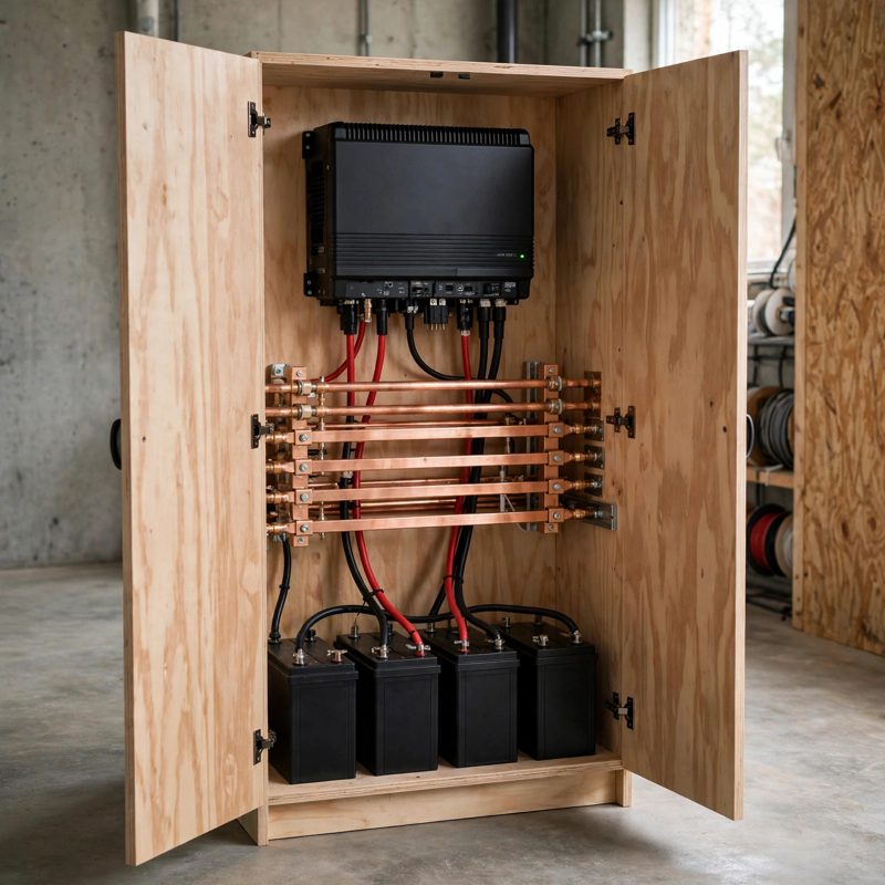
Not a standard off-grid kit. This is the top-of-the-line, above-and-beyond rebuild of the indoor half of an off-grid power system - the ventilated battery and control cabinet that ordinary kits replace with batteries on the floor and cables draped between them. Every claim below names a real feature drawn into the plan itself.
THE BUILD: a floor-standing 48 x 24 x 42 in cabinet (every stack summed two ways: plinth 4 + bottom 0.75 + battery bay 14 + divider 0.75 + control bay 21.75 + top 0.75 = 42.0 in) holding four 12.8V 100Ah LiFePO4 batteries in series (51.2V, 5.12 kWh - verified two ways: 51.2 x 100 and 4 x 1,280 Wh), copper bus bars, fused and labeled disconnects, and a 2,000W inverter on a stud-lagged backer board. Pairs with the Solar Power Shed, DIY Wind Turbine, and Micro-Hydro plans: they make the power, this cabinet stores, protects, and controls it.
FIVE THINGS ORDINARY KITS LEAVE OUT, ALL DRAWN IN: (1) SHORT-CIRCUIT PROTECTION AT THE BUS - an 80A Class T main fuse within 7 in of the positive bus, sized above the true worst-case load (56A at low battery and 85% inverter efficiency - not the friendly nominal 41.7A) and below the 2 AWG cable's 115A ampacity, both sides of the rule printed; branch fuses likewise (25A controller, 30A loads), and a clear cover living over both bus bars. (2) VENTILATION DRAWN HONESTLY BY CHEMISTRY - LiFePO4 does not off-gas in normal use, so its vents are sized for heat with the math shown (80 CFM fan against a 61 CFM absolute worst case and a 31 CFM sustained case); the lead-acid substitution path instead gets the high hydrogen exhaust and the no-ignition-source rule for the top 6 in, printed where the substitution is made. (3) THERMAL-RUNAWAY SPACING - batteries 1 in apart (row check: 4 x 6.77 + 3 x 1 = 30.08 in inside 46.5 in clear) with 5.57 in of headroom, never packed, never stacked, weight low on a bearing chain (panel ON plinth ON floor). (4) CABLE SIZING WITH THE DROP SHOWN - 2 AWG mains at 0.052V drop (0.11%) at worst-case load, computed two ways, because cabinet layout IS cable sizing; a fill-in worksheet re-sizes everything for YOUR inverter and YOUR bank. (5) DISCONNECTS A STRANGER CAN RUN - numbered in a printed shutdown order on the door card (source, battery, inverter), each one PROVEN in commissioning to kill what its label says.
HONEST SCOPE, PRINTED UP FRONT: this is the DC / low-voltage cabinet. Household AC, house panels, and transfer switches are flagged as licensed-electrician checkpoints - the plan draws the line where the law draws it and never pretends otherwise.
BEGINNER-FIRST, IN DEPTH: terms defined at first use (bus bar, ampacity, Class T, shunt, bite, bearing), a practice section (crimp pulled apart and cut open, torque learned on scrap, labels at both ends, the prove-measure-prove meter routine) before any real cable, 34 continuously numbered steps, 12 labeled diagrams - one at every technique step - a stop-and-check after each stage, mistake fixes for every stage, every fastener bite-checked (including the hinge-screw trap: 1-1/4 in screws in the 3/4 in door leaf would exit the face), sourcing with a good/better path and a spares box stocked inside the build, and a final checklist.
You receive: the PDF plan only (digital download, no physical product ships) with materials list, cut list, full two-way verification section, and commissioning steps. Full build plans and material list in the TheWorkshopBlueprint website store at theworkshopblueprint.shop.