
Mobile Miter Saw Stand Plan
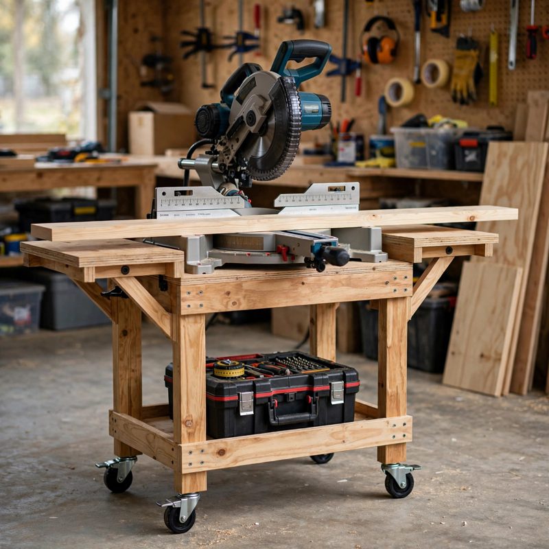
Not a standard off-grid kit - top-of-the-line, above and beyond the old style - safer by design, and every claim below names a real feature drawn into the plan itself.
THE BUILD: a mobile miter saw stand, main frame 36 x 24 in, with two folding wings (22 x 24 in each) that open to an 80 in span and finish level with your saw's own table. This is not a general workbench (flat top, one fixed height, no saw-level stock support), not a router cabinet (no router is carried or enclosed), and not a tool chest (no drawers; the lower shelf is open storage rated 40 lb). It does one job: long stock supported exactly at deck level on both sides of YOUR saw, with a fence and a repeatable stop on each wing, then folded to a 36 in footprint and rolled away on four total-lock casters.
NO UNIVERSAL HEIGHT - A WORKSHEET INSTEAD: miter saws differ in the distance from the bottom of the base to the table (the saw offset), so any stand built to one fixed wing height matches almost no saw. This plan makes you measure YOUR saw's offset and YOUR casters' overall height, choose YOUR deck height, and compute the platform height and leg length from them (worked example: deck 36 in, offset 4-1/2 in, platform 31-1/2 in, leg 24-1/4 in) - and every sum is worked two ways, with a straightedge proof against the actual deck before the wings are built and again after levelling (no rock, no light gap over 1/32 in).
IT DOES NOT TIP WITH A WING LOADED - MATH TWO WAYS, THEN A TEST: caster contact centres span 32-1/2 x 20 in. At the 50 lb per-wing design load centred 36 in from the stand centreline, moments about the tipping line give a restoring 1,950 in-lb against an overturning 987.5 in-lb (safety factor about 1.97, using a deliberately rounded-down 120 lb central weight and taking no credit for the support arms); the resultant method puts the combined weight's action point at about 10.6 in from centre, about 5.6 in inside the 16-1/4 in tipping line. Both ways agree. The plan then gates the build with a mandatory loaded stability test step: a weighed 50 lb load at the left wing tip, the right wing tip, and both together, plus 20 lb push tests - any caster lift or creep fails the build until fixed, and the wing limit for your actual build weight is computed by worksheet and labelled on the stand.
WINGS CARRIED IN COMPRESSION, NOT BY HINGES: each wing is located by two butt hinges and carried by a pin-in 2x2 support arm running from a frame bracket 8-1/2 in above the floor to a wing bracket 19 in out from the hinge line (rise 24-1/4 in, run 19 in, length 30-13/16 in - worked by Pythagoras and by angle, matching). At the full 50 lb wing load the arm's axial compression load is about 60 lb; both 1/4 in pins per arm sit in double-shear clevis brackets, and an unpinned wing is an unloaded wing by the plan's stated rule.
THE SAW IS NEVER DRILLED: the saw bolts through its OWN factory base holes into a 26 x 20 in plywood mounting plate (thread showing past every nut, proved on a scrap stack first), and the plate through-bolts to the platform at four corners outside the saw's footprint. If a hole does not clear, the plan says move the plate - never drill, ream, or slot the saw.
LOADS AND BEARING, STATED: saw plus cutting down-force 75 lb on the platform; worst rolling total 279 lb (stand about 94 lb, weighed two ways in the plan, plus saw 45 lb, both wings loaded, shelf 40 lb) on four casters rated 150 lb each - 600 lb total, about 2.15 times the load. Every working load rests on a dimensioned support: legs bear on flat foot rails over their full 1-1/2 x 3-1/2 in footprints, the platform bears on the leg tops, the shelf bears on its cleats, and every screw and bolt in the plan has its reach checked (apron screws bite 1 in; caster bolts are through-bolts, never lags into end grain).
FENCE AND STOPS THAT REPEAT: each wing carries a fence strip proved coplanar with the saw fence's face by a straightedge test (no eyeballing) and a sliding stop block that locks on a witness line; the plan's test-cut stage requires five pieces cut against the stop to agree within 1/32 in, and a blade-clearance check of at least 1/4 in at every miter and bevel setting, done with the saw unplugged.
BEGINNER-FIRST, IN DEPTH: every term defined at first use (deck, saw offset, platform, mounting plate, support arm, fulcrum, resultant, total-lock caster, fence strip, stop block, bite, bearing), a practice-first stage proving the frame joint and both bolt stacks on scrap, 28 continuously numbered steps in 7 stages, 12 labelled diagrams placed at their steps, a stop-and-check after every stage, mistake fixes (wings off deck level, a sagging wing, a failed stability test, a creeping stop block, stock catching the wing edge, a fluttering caster, a shifted saw), good/better materials (pine vs clear pine or fir, standard vs Baltic-birch-style wing and plate stock, polyurethane-wheel casters at the same rating and lock), and sourcing with exactly what to order - including the lumber yield math (7 boards of 2x4 for 393 in of frame parts; one 4 x 8 plywood sheet yielding all 2,908 sq in of plywood parts) - with costs labelled estimates totalling $210-$300.
You receive: the PDF plan only (digital download, no physical product ships) with cut list, materials list, height worksheet, full two-way verification section, and final completion checklist. Full build plans and material list in the TheWorkshopBlueprint website store at theworkshopblueprint.shop.