Freestanding Kayak & Canoe Storage Hoist Frame Plan - A-Frame Gantry with Pulley Hoist, Stores 2 Boats Overhead
Not a standard off-grid kit - top-of-the-line, above and beyond the old style - safer by design, and every claim below names a real feature drawn into the plan itself.
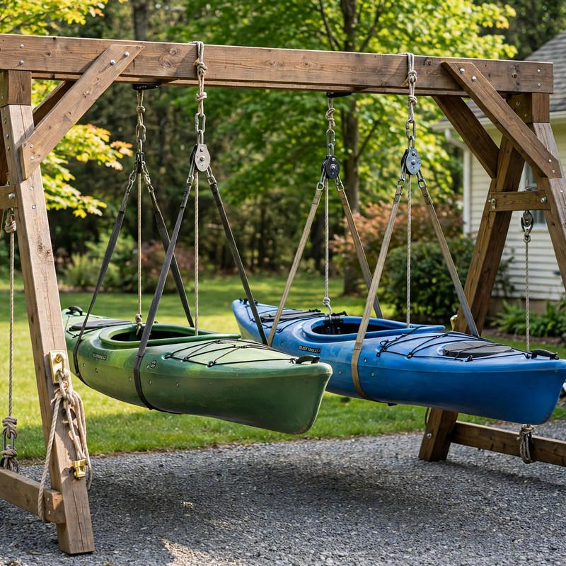
DISTINCT FROM OUR GROUND RACK: TheWorkshopBlueprint already sells a ground-level kayak rack that holds boats on padded arms near the floor. This plan is a different machine: an overhead A-frame gantry (144 x 96 in footprint, about 110 in tall, about 102 in clear under the beam) with an independent pulley hoist over each of two bays, lifting 2 kayaks or canoes off the floor and storing them overhead so the floor underneath is free again.
SAFER BY DESIGN - THE OVERHEAD FAILURES ARE DESIGNED AGAINST: (1) THE HEADLINE RULE is printed first and written on the beam in the plan: never walk under a suspended boat, and the operator works every lift from a side cleat, outside the drop zone. (2) SECONDARY SAFETY STRAPS ARE MANDATORY AND DRAWN IN: two independent straps per boat, on their own through-bolted beam anchors, carry every stored boat - the hoist rope is eased to a snug third restraint, so no boat ever hangs on a hoist rope alone. (3) THE LIFT IS HONEST: a true 4-to-1 pulley system per bay, with friction counted instead of wished away - ideal pull 30 lb, real pull about 38 lb for the 120 lb design load, worked both ways in the plan. (4) THE FRAME IS PROOF-TESTED BEFORE IT IS TRUSTED: a gated 180 lb sandbag proof test (1.5 times the design load), held 10 minutes per bay with every joint inspected, dated on the beam, before any boat goes up. (5) HULLS CANNOT ROLL OUT: two padded sling straps per boat, spaced along the hull, instead of a single central sling. HONEST LIMITS, printed in the plan: the 120 lb per-hoist design load is a planning figure, not a certified capacity; the heaviest boat class is 100 lb, verified by weighing each boat; and the tip math covers a straight lift on flat ground only - hoisting in wind, dragging the frame, and moving it loaded are banned outright.
EVERY MEASUREMENT VERIFIED TWO WAYS: footprint by beam (144 in) and by bays (66 + 6 + 66 + 6 = 144 in); height by Pythagoras (120 in legs at a 48 in half-spread give about 110 in) and by the cosine check; mechanical advantage ideally (4 parts, 30 lb) and with friction (effective 3.2-to-1, about 38 lb); rope length by falls math (46 ft minimum) against the 60 ft ordered; ratings against load (rope about 3,000 lb breaking / 300 lb WLL vs 120 lb = 25-to-1 and 2.5 times; each sling strap about 60 lb actual vs 500 lb WLL, about 8 times); tip resistance by moments (20,640 vs 2,750 in-lb, about 7.5-to-1) and by tip geometry; beam span by inset math and by bay layout (108 in both ways); every fastener reach-checked, including the apex bolts (7 in path, 8 in bolt specified).
BEGINNER-FIRST, IN DEPTH: every term defined at first use (gantry, A-frame, mechanical advantage, working load limit, safety factor, proof test), a practice-first stage proving the pulley pull, the diagonal square check, and the bite joint before real lumber, 34 continuously numbered steps in 6 stages, 12 labelled diagrams placed at their steps - including the rigging figure with the safety straps drawn in - a stop-and-check after every stage, mistake fixes (tilted hang, rolling hull, heavy pull, racking frame, slipping cleat, uneven safety straps, a bowed beam), a good/better materials path (stainless rigging, sewn-sleeve straps, doubled hoist anchors), and sourcing with every price labelled an estimate.
You receive: the PDF plan only (digital download, no physical product ships) with cut list, materials list, full two-way verification section, and final completion checklist. Full build plans and material list in the TheWorkshopBlueprint website store at theworkshopblueprint.shop.